
How does the heat pump work ?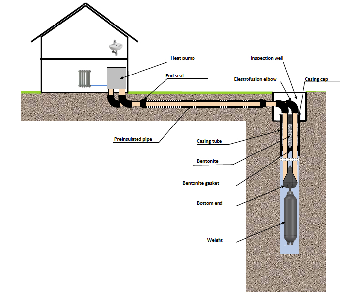
THE GEOTHERMAL HEAT PUMP TECHNOLOGY
Introduction
The second law of thermodynamics is fundamental to understand the heat pump process. The second law of thermodynamics states that the heat in the nature – always flows from hotter to colder places. A simple example – after boiling an egg, we cool it down in water. The heat leaves the egg and heats the water… The flow will never go the reverse way – unless external work is performed on the system.
The third law of thermodynamics states the theoretically lowest temperature is the null or zero point. The thermodynamic temperature is a measure of the average kinetic energy from the motions in the molecules and atoms. At zero point, the molecules and atoms are at rest. The third law of thermodynamics explains – in an easy way – why the temperature always flows from hotter to colder places.
The Heat Pump Process
General
A geothermal heat pump has 2 internally connected circuits which we call “The cold side“ (Evaporator) and “The hot side“ (Condenser). In the interconnected circuits, a refrigeration medium is circulated by a compressor. The refrigerant medium absorbs and removes heat from the ground and rejects the heat into the condenser. The refrigeration medium switches between gas- and liquid phases. The switching of phases is governed by a so-called expansion valve.
Refrigeration mediums – Refrigerants
There are basically 2 types of refrigerants; synthetic and natural. DuPont, DOW Chemical and LINDE are large producers of synthetic refrigerants. These refrigerants, unfortunately all have a large global warming potential (GWP). Example: 410 A: GWP = 2088. Natural refrigerants like propane (R 290) and CO₂ carbon dioxide (R 744) are gradually gaining larger attention and use in the market. Example: R290: GWP = 3
The cold side (Evaporator)
To take advantage of the natural flow of the heat in the ground, the temperature of the refrigeration medium (Liquid phase) should be around – 8 ºC (Evaporator temperature) at the end of the heating season. At -8 ºC, the heat energy from the soil/rock will still flow over into the colder evaporator circuit. Normal ∆T in the “Cold side“ is 2 – 3ºC here in Scandinavia.
The hot side (Condenser)
The much higher temperature at the “Hot side“ is created by the compressor. The compressor elevates the temperature of the refrigeration medium (Gas phase) in the condenser to 65 – 70ºC (Radiator systems). The condenser heat will automatically flow over into a 55 – 45 º C (colder) water circulated heating system in the house. Normal ∆T in the “Hot side“ is 7 – 10 ºC in a radiator system. With floor heating systems, condenser temperature can be lowered to 45 – 55 ºC. Normal ∆T in the “Hot side“ is 5 – 8 ºC with floor heating.
Thermal efficiency – COP – (Coefficient of Performance) for Heat Pumps
A heat pump moves 3 – 4 times more heat energy than the electric energy it consumes. This results in net thermal efficiencies greater than 300% as compared to radiator electric heat being 100% efficient.
Importance of the “Temperature Lift“
The efficiency of a geothermal heat pump is directly related to the inlet temperature from the heat source – and to the outlet temperature from the condenser. An example: With the refrigerant R290 – the compressor operating pressures will be as follows: Condensing temperature: Compressor pressure: 35 ºC 12.3 Bar (Floor Heating), 55 ºC 19.4 Bar (Radiator Heating), 65 ºC 23.8 Bar (Radiator Heating). A typical COP for floor heating systems will be 4.0 – 4.5. A typical COP for radiator heating systems will be 3.0 – 3.5.
Vertical Heat Exchangers – “Energy Collectors“
General
To maintain a heat pump process, energy must continuously be transferred from the heat source and into the evaporator- which is typically a plate type heat exchanger. To transfer the geothermal energy from the ground and into the evaporator, a separate heat exchanger has to be installed in the borehole.
Vertical heat exchangers – “Energy Collectors“
PE-type pipes are most widely used as heat exchangers in boreholes. The PE-material itself is not a good material regarding thermal conductivity – only 0.4 W/(m·K). As a comparison – thermal conductivity of copper is 390 W/(m·K). Thermal conductivity of water is 0.6 W/(m·K) and ice 2.2 W/(m·K). The PE-pipes – however – are cost effective and operator friendly. Various attempts have been made – for many years – to introduce other types of energy collectors here in Scandinavia. So far – the new collector systems have not been able to compete with the well proven PE-type collectors with bottom type U-bends.
Dimensioning of geothermal energy collectors on the Scandinavian peninsula
Introduction
To dimension bore holes with a high degree of accuracy, thermal responsively testing (TRT-testing) has to be performed. A TRT-test will give input necessary data for calculation of the thermal conductivity and the thermal resistance of the rock. The below figures must be considered as guide lines – only. Experience through many years has – however – confirmed that the below guide lines are conservative and realistic.
Factors to be taken into consideration:
1). The climatic conditions (Climatic Zones)
2). The thermal conductivity of the rock – λ-value
3). The distance and type of overburden material
4). The static ground water level
5). The ground temperature
6). The size of the heat pump.
7). Type of heating system – radiators or floor heating
8). The heat pump power coverage (Example: 60% power coverage will give 93% energy coverage)
9). Type and diameter of collector pipe
Re. Point 4).
The geothermal energy cannot be transferred into the collector unless there is a thermal convection medium in the borehole. Water is normally the thermal convection medium. When estimating necessary drilling length, only the length filled with water must be taken into consideration (“Active borehole length“). In dry holes – or holes with a long distance to the static water level – back filling with bentonite or quartzite sand is a good solution.
Re. Point 5).
The ground temperature will normally be ~ 2ºC higher than the average mean temperature for a given location.
The Geological Surveys of Norway (NGU), Sweden (SGU) and Finland (GTK) have prepared ground water isotherm charts for the respective countries.
Re. Point 6).
The first thing to know is the size of the heat pump.
From thermodynamics we know that the cooling capacity of a heat pump is ~ 70% of the heating capacity.
An example – located in Climatic Zone C:
A heat pump has a heating capacity of 160 kW at 0/50ºC.
The cooling capacity (load on the collector) will be: (160 x 0.7) kW = 112 kW = 112.000 W
Recommended, minimum drilling distance: 112.000 : 35 = 3.200m
Can be performed as:
16 boreholes á 200 m (active)
In practice: 16 boreholes á 210 m – assuming 10m distance to the static ground water level.
Re. Point 7).
The efficiency of a heat pump is closely related to the temperature lift – see above.
A heat pump with floor heating is more efficient than a heat pump connected to radiators.
A floor heating heat pump will exert a higher load on the collector than a radiator-type heat pump.
Ideally – the boreholes should be 5% longer with floor heating than with radiator heating.
Re. Point 8).
With the commonly used start/stop-type heat pumps, it is normal to select a heat pump which covers 40 – 70% of the dimensioning capacity of the building.
The relationship between power coverage and energy coverage is as follows:
Power coverage %: 30 40 50 60 70 80 90 100
Energy coverage %: 68 80 87 93 96 98 99 100
60% coverage will represent ~ 3500 hours of HP-operation (One year is 8760 hours).
The remainder will be covered by a heater element built in the HP.
NOTE:
Inverter type HP`s are now getting larger and larger market shares.
The inverter type HP`s are designed to give 100% power coverage.
When utilizing full power, the inverter type HP will create a higher load on the collector.
As a rule of thumb – boreholes must be 10% longer when connected to an inverter type HP.
Re. Point 9).
In built up areas, limited space has created a need of deeper bore holes. Now, projects with 250 – 300m and even 500m deep bore holes are getting more and more common. To overcome the pressure-drop in the deeper bore holes, larger size pipes is a better solution. Until 2 years ago, there was a gap in the pipe program between 40 and 50mm. Now 45mm pipes are available in the market; it is assumed that this dimension will the most commonly used size in wells deeper than 250meter.
Last – but not least – experience from the last decade has shown that collectors with inside rifles (fins) is a good solution. The rifles will ensure turbulent flow at a lower flow rate than smooth pipes, and the pressure-drop is also lower because the rifles acts as reinforcement which in turn insures that the ideal, circular shape is maintained.
Oslo, March 2018
Per Stykket – Manager Geothermal Heat Pump Systems – ABK AS
The simple scheme of house heating system based on the ground to water heat pump.